
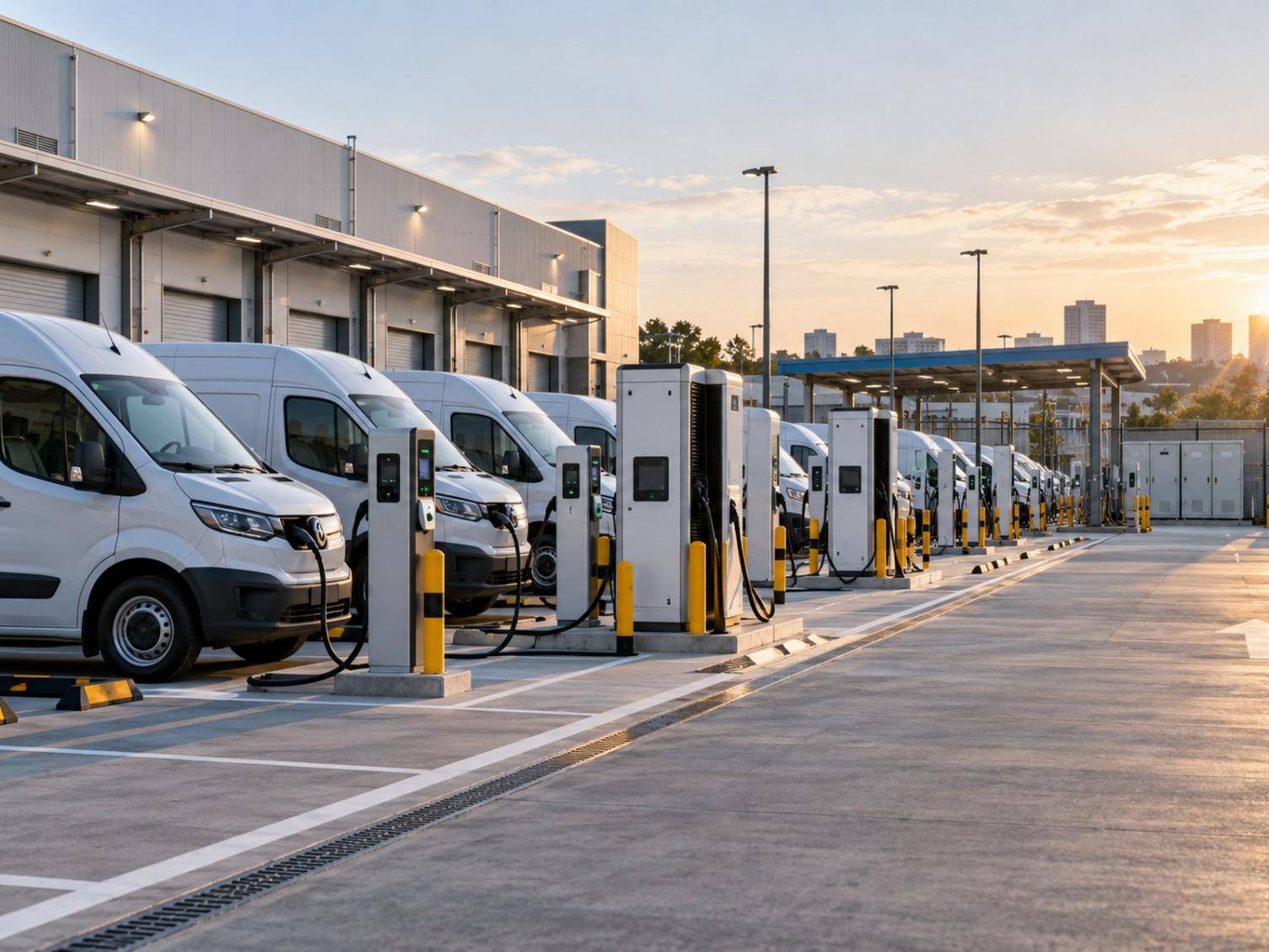
EV fleet charging infrastructure should be planned around fleet duty cycles, daily energy demand, return and departure windows, site electrical limits, and operational priorities. This article focuses on fleet depot infrastructure planning, scheduling, load management, charging-management-system connectivity, and scalable deployment rather than repeating a product-selection-only AC/DC comparison. U-charging supports this planning approach with configurable commercial charging equipment, model-dependent OCPP and load-management options, and project support that should be confirmed against the selected product specification before deployment.
Why Fleet Charging Requires Operational Planning
Start With Vehicle Duty Cycles
A fleet depot should be designed around vehicle operating schedules, route requirements, and charging demand patterns. Delivery vans may return in groups, taxis may stop briefly between shifts, and corporate vehicles may remain overnight. Recording arrival times, departure deadlines, route length, and minimum state-of-charge requirements helps identify vehicles suitable for lower-power charging and those requiring priority charging access.
Map Dwell Time and Departure Windows
Dwell time is one of the primary design parameters for determining appropriate charging power levels. Vehicles parked for several hours can use AC charging, while vehicles with short turnaround windows may need DC capacity. The plan should also identify simultaneous return periods because a depot designed around average demand can struggle when an entire shift arrives together.
How to Size EV Fleet Charging Solutions
Audit Vehicles and Daily Energy Needs
Group vehicles by duty cycle, battery requirements, onboard AC acceptance, connector, and the energy that must be restored before departure. Avoid applying one assumed charging duration to the whole fleet. Vehicle limits, battery state, temperature, charger availability, and site conditions can all change actual charging performance.
Review Available Site Capacity
The electrical review should cover the service connection, transformer, distribution equipment, protection, grounding, cable routes, and capacity assigned to charging. Lighting, workshops, offices, refrigeration, or other depot loads may share the same supply. Dynamic Load Management (DLM) and smart charging functions can optimize charging power based on available electrical capacity, energy tariffs, and operational priorities.
Plan for Phased Fleet Expansion
A scalable design reserves conduit routes, panel space, network coverage, physical bays, and service clearances for later phases. Start with vehicles and routes that have predictable schedules, then use operational records to refine the next stage. Expansion should respond to actual dispatch constraints rather than an unsupported universal charger-to-vehicle ratio.
Fleet Charging Project Inputs
Before selecting charger quantities or power levels, collect the minimum operating and site inputs below. These fields create the basis for energy, concurrency, scheduling, and expansion calculations.
|
Project input |
Required project data |
Why it matters |
|---|---|---|
|
Fleet Size |
Total vehicles in scope now and by expansion phase |
Defines charging positions, phasing, and utilization assumptions |
|
Vehicle Model |
Model, battery capacity, charging inlet, AC OBC rating, DC voltage/current acceptance |
Prevents charger-to-vehicle compatibility assumptions |
|
Daily Energy Demand |
kWh to restore per vehicle and for the fleet per operating day |
Sets the energy requirement that must fit inside the charging window |
|
Return / Departure Time |
Return distribution, earliest departure, latest departure, exception routes |
Defines usable dwell time and scheduling priorities |
|
Peak Concurrent Charging |
Expected maximum vehicles connected/charging at once |
Drives site peak demand and load-management requirements |
|
Available Site Power |
Utility/service capacity available to charging after other depot loads |
Defines the controllable charging capacity boundary |
|
Connector / Market Standard |
Vehicle inlet and required connector standard by region |
Determines cable/connector compatibility |
|
Expansion Plan |
Future fleet size, reserved bays, conduit, panel and network capacity |
Supports scalable deployment without assuming full build-out on day one |
Use measured fleet data where available. If assumptions are used, label them clearly and test peak-day and exception-route scenarios rather than relying only on averages.
Match AC and DC Chargers to Fleet Operations
AC Charging for Overnight and Long-Dwell Vehicles
U-charging 7/11/22kW Smart AC EV Charger offers 7kW, 11kW, and 22kW configurations, a single charging connector with a standard 5m cable, APP/RFID start methods, 4G/Wi-Fi/Ethernet/Bluetooth connectivity, OCPP 1.6J with OCPP 2.0 optional, IP55 protection, and protection functions including short circuit, overload, overtemperature, leakage, and overvoltage. The vehicle’s onboard charger (OBC) determines the AC power it can actually accept, so a 22kW charger does not imply 22kW charging for every vehicle. Final project specifications should be checked against the latest formal datasheet and ordered configuration.
|
Fleet condition |
Charging role |
Equipment direction |
Planning focus |
|---|---|---|---|
|
Long overnight dwell |
Routine recovery |
AC charging |
Departure time and vehicle AC acceptance |
|
Short turnaround |
Rapid redeployment |
Selected DC capacity |
Vehicle limit, site supply, and queue |
|
Mixed schedules |
Routine plus exceptions |
AC and DC mix |
Priority rules and bay allocation |
|
Many simultaneous returns |
Coordinated sessions |
Scheduled charging and DLB |
Configured site limit and control behavior |
DC Charging for Rapid Turnaround
DC charging can support rapid turnaround, but logistics vehicles, buses, and heavy-duty fleets must not be treated as universally compatible with every DC product. For each vehicle class, confirm the charging inlet/connector standard, vehicle DC voltage window, maximum charge current, maximum accepted power, cable reach, thermal-management requirements, communication requirements, and the selected charger’s output voltage/current range. U-charging 20-40kW DC with a 200-1000V DC output range and up to 125A and is positioned for light fleet charging; that specification should not be generalized to buses or heavy-duty vehicles. For bus or heavy-duty projects, obtain and approve the formal datasheet for the selected model and verify compatibility with the vehicle OEM before equipment selection.
Use a Mixed Charging Strategy
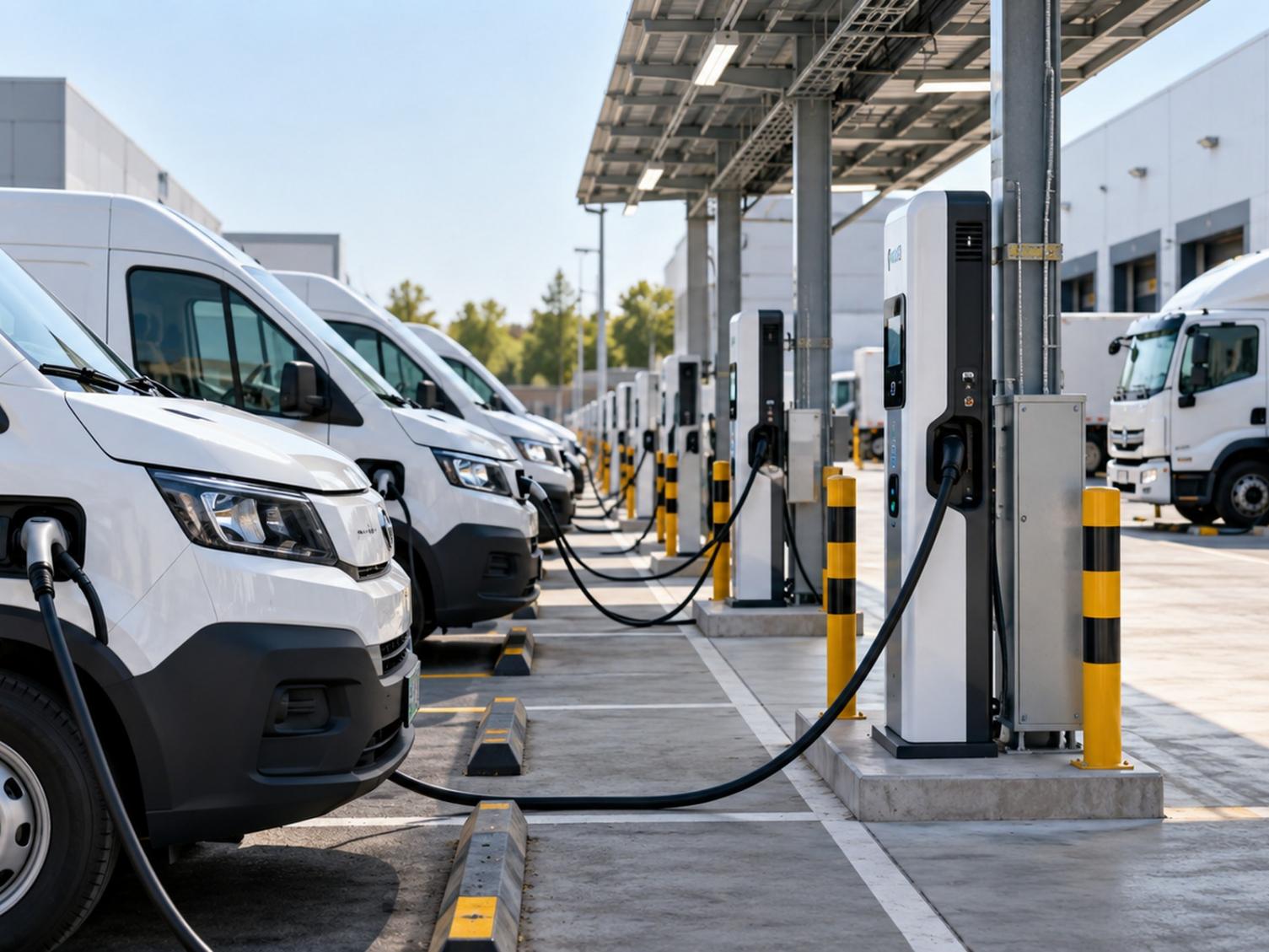
A mixed depot can assign AC charging for routine overnight recovery and reserve DC charging for vehicles requiring shorter turnaround times or higher operational availability. This avoids oversizing every charging bay based only on maximum charger power requirements. The operating policy should state which vehicles receive DC priority and when they return to standard AC rotation.
Coordinate Charging Across a Large Depot
Apply Scheduled Charging
Scheduled charging can align sessions with vehicle availability, departure time, and the depot’s planned energy window. Vehicles should be grouped by the time they must leave rather than simply by arrival order. Operators also need an exception process for a replacement vehicle or an urgent route change.
Use Dynamic Load Balancing
Dynamic Load Balancing can distribute available capacity among compatible charging points according to a configured site boundary. It is particularly relevant when many vehicles connect after a shift. The selected charger, control architecture, measurement method, and priority rules must support the intended behavior before the function is included in a fleet plan.
Set Vehicle and Driver Priorities
RFID, app, or card activation can identify authorized users or groups depending on configuration. A depot may assign access by vehicle class, operating team, or charging zone. Clear priorities help staff understand charging priority allocation rules and reduce informal overrides that weaken the schedule.
Fleet Depot Planning Example — Illustrative Example
Illustrative Example only — the values below are hypothetical planning inputs and do not represent a delivered U-charging project or guaranteed operating result.
|
Project input |
Illustrative assumption |
|---|---|
|
Fleet size |
24 electric delivery vans |
|
Vehicle assumption |
60kWh usable battery; Type 2 AC inlet; 11kW AC OBC; DC capability to be verified by vehicle model |
|
Daily energy demand |
45kWh average replenishment per vehicle; 1,080kWh total daily charging energy |
|
Return / departure window |
Most vehicles return 18:00-20:00; departures 06:00-08:00 |
|
Peak concurrent charging |
18 vehicles connected during the evening return wave |
|
Available site power for charging |
350kW controllable charging limit after other depot loads |
|
Planning approach |
Schedule routine overnight charging within the site limit; reserve selected DC capacity only for short-turnaround exceptions after vehicle compatibility is confirmed |
|
Expansion allowance |
Reserve conduit, switchboard space, network capacity, and bays for a future 36-vehicle fleet |
Planning logic: 1,080kWh must be delivered within the overnight operating window while the charging system remains inside the 350kW site boundary. Because the example vehicle accepts up to 11kW AC, charger nameplate power above that AC acceptance would not increase its AC charging rate. The charging-management system and any DLM strategy should therefore prioritize departure deadlines and exception vehicles, then validate the schedule with real return-time and energy data during commissioning. This example illustrates planning logic only; it does not state a fixed charger count, utilization rate, or project outcome.
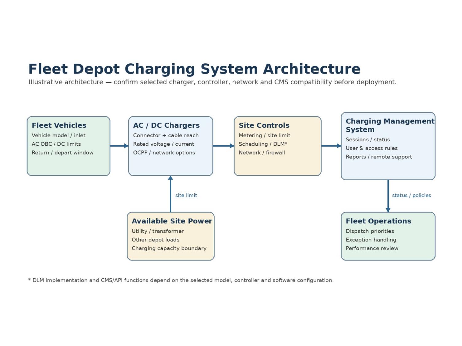
Connect Chargers to a Charging Management System
Confirm OCPP Compatibility
OCPP should be treated as a protocol capability, not proof of compatibility with every charging management system or third-party fleet platform. Our 7/11/22kW Smart AC product with OCPP 1.6J and OCPP 2.0 is optional; OCPP 2.0.1 is not assumed here. Before deployment, confirm the selected charger model, firmware, protocol version, backend endpoint, required OCPP profiles, permissions, transaction workflow, and data fields with the charging management system provider.
Select Network and Access Methods
Communication methods are model-dependent. 7/11/22kW Smart AC equipped with 4G, Wi-Fi, Ethernet, and Bluetooth. The depot design should also define network coverage, firewall and SIM requirements, offline behavior, user authentication, data ownership, and support responsibility before commissioning.
Use Remote Monitoring and Diagnosis
Remote monitoring, upgrade, and diagnosis can support charger operations when the selected hardware, firmware, network, and charging management system provide those functions. Operators should define which alarms, session data, remote actions, and service workflows are required, and confirm them during FAT/SAT or commissioning rather than assuming identical remote-management capability across all models.
Design a Practical Fleet Charging Site
Arrange Bays Around Vehicle Movement
Charging bays should follow the depot’s circulation pattern so connected vehicles do not block dispatch lanes, loading areas, or each other. Check cable reach against vehicle inlet locations and preserve turning space for larger vehicles. DC bays may need a different traffic pattern from overnight AC rows.
Protect Cables and Service Areas
Wheel stops, impact protection, drainage, lighting, connector holders, and clear pedestrian routes support daily use. Technicians need safe access to cabinets and distribution equipment without moving an entire fleet row. Protection functions such as overcurrent, short circuit, leakage, overvoltage, and overtemperature depend on the selected configuration and complement correct site design.
Prepare Electrical and Network Infrastructure
Electrical and communication routes should be coordinated before concrete, barriers, and bay markings are finalized. Document circuit identification, network settings, access roles, and isolation procedures during commissioning. A consistent handover makes later troubleshooting and expansion easier across multiple depots.
Where U-charging Fits Fleet Projects
Logistics and Delivery Fleets
Logistics and delivery fleets are a primary depot-infrastructure use case because return waves, route energy demand, loading operations, and fixed departure deadlines can be modeled together. Scheduled AC charging can serve vehicles with stable overnight windows, while selected DC capacity can be reserved for exception routes or short turnaround requirements. Connector standard, vehicle voltage/current acceptance, cable reach, bay geometry, and the selected equipment specification must be verified for each vehicle model before the plan is finalized. A phased design can then add charging positions as electric routes expand.
Taxi and Ride-Hailing Operations
Taxi and ride-hailing vehicles often have shorter, less predictable idle periods, making DC availability more important. Operators should still avoid selecting equipment only by maximum power. Vehicle compatibility, site capacity, connector arrangement, queuing, and service coverage determine whether the station supports reliable shift turnover.
Corporate and Mixed-Use Fleets
Corporate fleets may combine pool cars, assigned vehicles, visitors, and employee charging. AC equipment can support routine long stays, while controlled DC access can cover urgent operational needs. Separate access groups and charging zones help prevent nonessential sessions from displacing vehicles with scheduled departures.
How U-charging Supports Fleet Depot Projects
Fleet projects require coordination across vehicle data, electrical capacity, charger specifications, software, and operating procedures. U-charging project support can be structured around the following scope, subject to project agreement:
|
Project stage |
U-charging support focus |
|---|---|
|
Product selection |
Match AC/DC equipment to vehicle connector, voltage/current acceptance, dwell time, and operating environment. |
|
Depot planning |
Review charging windows, peak concurrency, site capacity, bay layout, cable reach, and phased expansion requirements. |
|
Equipment supply |
Confirm model configuration, connector/cable options, communications, protection functions, and project documentation. |
|
Installation & commissioning coordination |
Coordinate interfaces with the installer/EPC, network setup, functional checks, and handover requirements. |
|
OCPP / CMS integration coordination |
Confirm protocol version, backend requirements, test cases, permissions, and remote-operation functions for the selected configuration. |
|
Training & remote after-sales support |
Support operator handover, basic troubleshooting workflows, remote diagnosis/upgrade where supported, and service escalation. |
Conclusion
Effective EV fleet charging solutions begin with routes, return times, departure deadlines, and electrical limits. Matching those conditions to AC, DC, scheduled charging, and load management creates a depot that supports vehicle availability without treating every session as equally urgent.
U-charging can support fleet charging projects from product selection and specification confirmation through depot planning, equipment supply, installation and commissioning coordination, charging-management-system/OCPP integration coordination, operator training, and remote after-sales support, subject to the scope agreed for each project. This project-support approach helps align charger capability with vehicle compatibility, site power, operating schedules, and future expansion.
Get Fleet Charging Solution | Talk to Our Engineer | Request Product Datasheet — share Fleet Size, Vehicle Model, Daily Energy Demand, Return/Departure Time, Peak Concurrent Charging, Available Site Power, Connector Standard, Project Location, and Expansion Plan so the proposed charger configuration and depot architecture can be reviewed against your operating requirements.
FAQ
Q: How many chargers does a large EV fleet need?
A: There is no universal charger-to-vehicle ratio. The answer depends on vehicle energy needs, return times, departure deadlines, dwell duration, charger availability, site capacity, and route exceptions. Model the busiest operating window, assign priorities, and reserve expansion space instead of sizing the depot only from the average number of vehicles parked.
Q: Should a fleet use AC or DC chargers?
A: AC charging generally suits vehicles parked for several hours or overnight, while DC charging supports shorter turnaround requirements. Many large fleets benefit from a mixed system that uses AC for routine recovery and reserves DC for time-sensitive vehicles. The final choice must also reflect vehicle compatibility and available electrical capacity.
Q: How does Dynamic Load Balancing support fleet charging?
A: Dynamic Load Balancing coordinates compatible chargers within a configured electrical limit. It can allocate available capacity when several fleet vehicles connect at once and may work alongside scheduled charging or priority rules. It does not add electrical capacity, and its exact behavior depends on the selected equipment, measurement method, and control configuration.