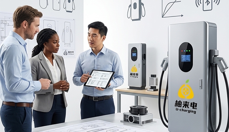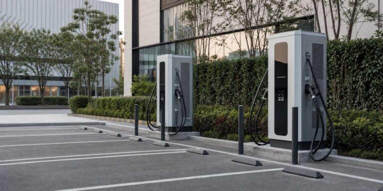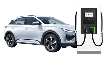
Fleet EV charging solutions should be designed around when vehicles return, how far they travel, how long they remain parked, and when they must leave again. AC charging can serve vehicles with long depot dwell times, while DC fast charging can replenish battery energy and restore vehicle state of charge (SOC) within shorter operational windows. The optimal charging layout is therefore an infrastructure planning decision based on power requirements, vehicle schedules, and operational constraints.
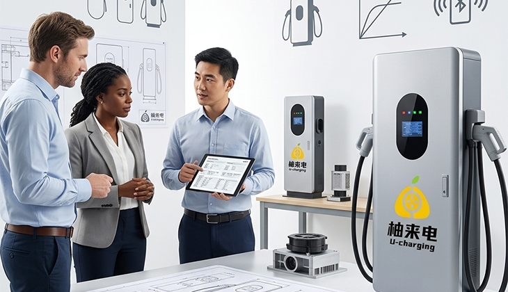
U-charging provides a 7kW / 11kW / 22kW smart AC option for predictable long stays and a 120–240kW DC fast charger with an optimized air-cooling design for high-utilization fleet operations. Combining the appropriate equipment with clear parking, electrical, and connectivity planning helps a fleet build charging capacity without separating hardware decisions from daily operations.
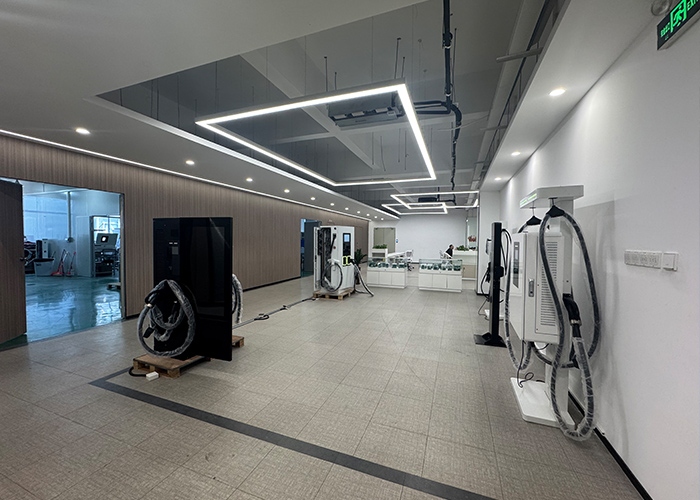
Start With the Fleet Operating Cycle
Every fleet has a different charging window. Delivery vehicles may return in waves, service vehicles may park overnight, and pool cars may leave several times per day. Mapping arrival time, departure time, route distance, and required availability reveals where slower AC charging is sufficient and where DC capacity may be necessary. The plan should also account for vehicles that return later than expected or begin the next shift with a lower battery SOC or higher daily energy demand.
Group Vehicles by Dwell Time
Vehicles parked through a full night or extended dwell period are often suitable for AC charging, depending on battery capacity, daily mileage, target departure SOC, and onboard charger capability. Units with short breaks, unpredictable dispatches, or multiple daily shifts may need access to DC fast charging, depending on their charging capability and the site’s available electrical capacity.
Grouping vehicles by operating pattern also improves parking discipline. Dedicated charging lanes, clear cable reach, and an agreed rotation process reduce the chance that a fully charged vehicle reduces charger availability for subsequent vehicle operations.
Choose AC Charging for Predictable Depot Stays
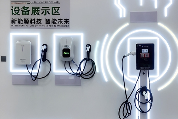
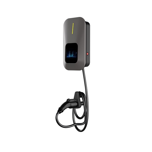
The U-charging 7kW / 11kW / 22kW Smart AC EV Charger is available in 7kW, 11kW, and 22kW configurations. It supports wall-mounted or pedestal installation, includes a 5-meter charging cable and touchscreen, and carries an IP55 enclosure rating for outdoor operation. APP control, RFID access, and smart charging functions allow fleet operators to manage access, charging schedules, and energy usage more efficiently. The product also supports 4G, Wi-Fi, Ethernet, Bluetooth, and OCPP 1.6J, allowing it to connect with an operating platform when the selected software and deployment are compatible.
AC equipment can be distributed across overnight parking bays or assigned to vehicles with repeatable schedules. The vehicle’s onboard charger determines the AC power it can accept, so a 22kW station will not deliver 22kW to every vehicle; vehicle capability must remain part of the configuration decision.
Fleet AC/DC Charging Selection Table
| Fleet Requirement | AC Charging | DC Fast Charging |
| Overnight parking | ✓ Suitable | Optional |
| Long vehicle dwell time | ✓ Suitable | Usually unnecessary |
| Short turnaround time | Limited | ✓ Suitable |
| Multiple shifts per day | May be insufficient | ✓ More suitable |
| High daily mileage | Depends on dwell time | ✓ Often suitable |
| Predictable charging schedule | ✓ Suitable | ✓ Suitable |
| Limited grid capacity | ✓ Easier to distribute | Requires careful planning |
| Need rapid energy replenishment | Limited | ✓ Suitable |
| Typical fleet application | Pool cars, service vehicles, overnight fleets | Delivery fleets, commercial vehicles, multi-shift operations |
The selection should ultimately be based on vehicle battery capacity, onboard charging capability, daily energy consumption, available dwell time, and site electrical capacity rather than charger power alone.
Use DC Fast Charging for Shorter Turnarounds
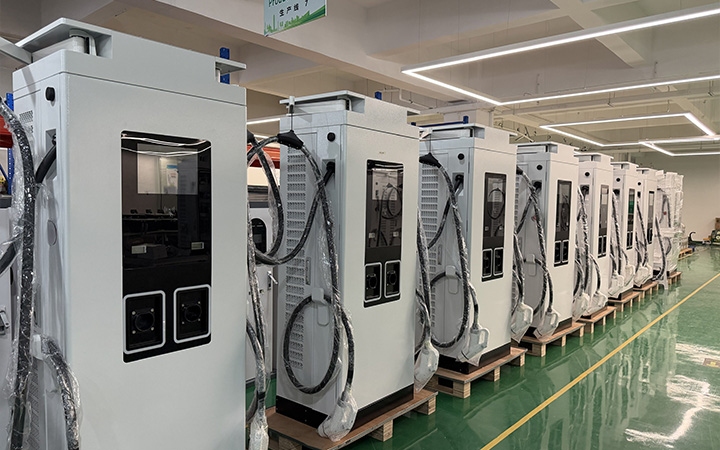
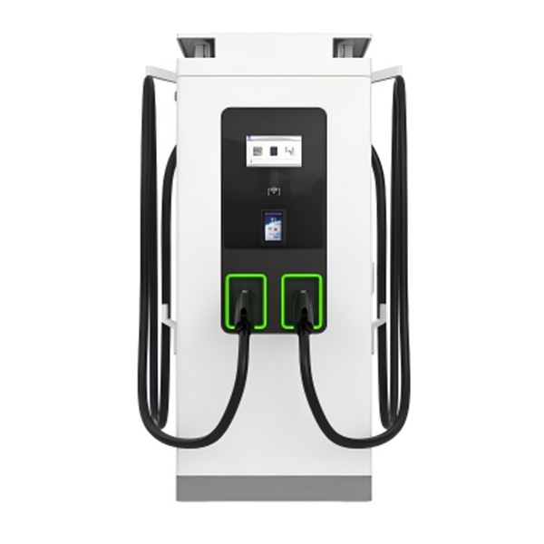
The U-charging 120–240kW Low-noise DC Fast Charger series covers a power range of 120–240kW and supports a 200–1000V output range. The unit includes a 10.1-inch touchscreen with APP and RFID starting methods; POS is available as an option.
The charger supports 4G, Wi-Fi, Ethernet, Bluetooth, and OCPP 1.6J. Its IP54 enclosure and optimized air-cooling design support commercial and fleet charging applications where effective thermal management is required. A fleet can position DC equipment for vehicles with the shortest turnaround or highest daily utilization. The dual-gun structure provides two physical charging connections, but the available information does not define simultaneous power allocation, so the operating plan should not assume a particular split between vehicles.
Plan the Depot Electrical Infrastructure
Charger selection must be coordinated with the depot’s distribution capacity, cable routes, parking geometry, drainage, impact protection, and maintenance access. Installing several chargers creates a combined site demand that may be more important than the rating of any single unit.
The design should consider how many vehicles may connect at the same time and whether all of them truly need maximum output. Because local grid, permitting, and electrical requirements differ, qualified professionals should confirm the final distribution and installation design for the project location.
Implement Dynamic Load Management for Fleet Charging
Dynamic Load Management (DLM) helps balance charging power among multiple EV chargers by adjusting output according to real-time site capacity. This can reduce peak demand and avoid unnecessary electrical infrastructure upgrades.
Position Chargers Around Vehicle Movement
Fleet charging spaces should support optimized vehicle circulation planning instead of creating inefficient vehicle maneuvering requirements, crossing active lanes, or stretching cables across walkways. The 5-meter cable on the U-charging AC product offers a useful placement reference, but the charger must still reach the inlet positions used by the fleet.
DC equipment needs enough space for vehicle approach, cable handling, cooling airflow, and maintenance. Where a depot operates around the clock, access to the charger should remain possible without interrupting other loading, parking, or dispatch activities.
Connect Charging With Fleet Management
Connected charging can help an operations team see which equipment is available and organize access across drivers or vehicle groups. RFID can support controlled starts, while network options provide routes for communication with a management platform, subject to the functions supported by the selected system.
OCPP 1.6J gives the AC and DC products a common protocol foundation. It should not be interpreted as automatic compatibility with every platform or as confirmation of every advanced software function, so commissioning requirements and operational workflows should be checked before deployment.
Design Fleet EV Charging Solutions for Expansion
A depot rarely needs to electrify every parking position at once. A phased fleet EV charging solution can begin with the vehicles that have the clearest routes and longest dwell times, while reserving electrical capacity, conduit paths, network coverage, and physical space for later additions.
An AC-first layout may suit service and pool vehicles parked overnight, with DC capacity added for high-mileage or multi-shift units. This mixed approach lets the fleet match equipment to operational urgency while maintaining a consistent plan for access, connectivity, maintenance, and future growth.
Set Clear Charging Responsibilities
Drivers and depot staff need simple rules for connecting vehicles, moving them after charging, reporting damage, and responding to a failed session. Defined operational responsibilities help maintain charger availability and reliability.
Maintenance planning should include charger inspection, cable condition, communication status, and safe access to equipment. Operating procedures must follow the product documentation and applicable local requirements rather than relying on generalized maintenance intervals.
Conclusion
Effective fleet EV charging solutions align charger power with vehicle schedules, depot capacity, and operational turnaround requirements. U-charging supports this approach with 7kW / 11kW / 22kW smart AC charging for long-dwell vehicles and 120–240kW low-noise DC fast charging for higher-utilization duties, backed by multiple connectivity options and OCPP 1.6J.
Planning a Fleet EV Charging Project? Share your fleet size, vehicle models, daily mileage, operating shifts, and available grid capacity with U-charging to discuss an AC, DC, or mixed charging configuration for your fleet. Explore U-charging EV charging solutions to learn more.
FAQ
Q: Should a fleet use AC chargers or DC fast chargers?
A: Fleets with long overnight parking windows can often use AC charging for much of their daily energy recovery. DC fast charging is more relevant for vehicles with short turnaround times, multiple shifts, or higher utilization. Many depots can combine both types and assign DC equipment to the most time-sensitive vehicles.
Q: What AC charging powers does U-charging offer for fleets?
A: The U-charging Smart AC EV Charger is available in 7kW, 11kW, and 22kW configurations. It supports wall-mounted or pedestal installation and includes a 5-meter cable. The appropriate configuration depends on depot capacity, parking duration, and the AC charging limit of each fleet vehicle.
Q: How can a fleet prepare its charging depot for expansion?
A: A fleet can reserve distribution capacity, conduit routes, parking positions, network coverage, and maintenance space before adding more chargers. Phased deployment allows the operator to begin with vehicles that have predictable schedules, measure practical charging needs, and preserve suitable areas for additional AC or DC equipment later.