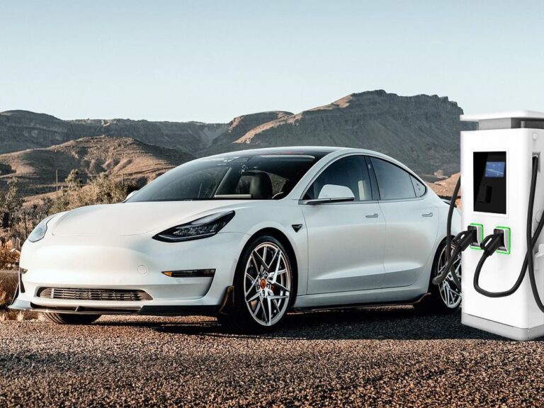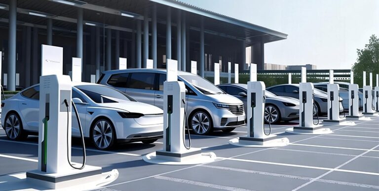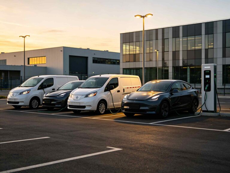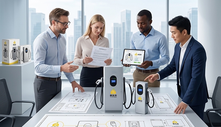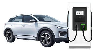
A reliable DC charging station deployment requires a structured engineering workflow covering site assessment, electrical design, installation, commissioning, and operational handover.
U-charging supports this workflow with DC configurations for public, commercial, fleet, and highway applications.
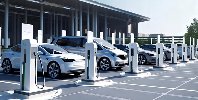
DC Fast Charging Station Site Assessment and Planning
Match Charger Power to Vehicle and Turnover Needs
Charging demand analysis should be completed before selecting charger power ratings. A fleet depot may prioritize scheduled readiness, a highway service area may require higher charging throughput and shorter vehicle dwell times, and a commercial parking facility may combine short-stay DC bays with longer-stay AC spaces. U-charging offers DC charging solutions ranging from compact 20kW / 30kW /40kW units to higher-power 120–240kW and 240–480kW systems, depending on the product configuration and market requirements.
Power ratings and available configurations should be confirmed against the selected product specification. For multi-outlet chargers, distinguish total charger capacity from per-outlet power and confirm how power is allocated during simultaneous charging.
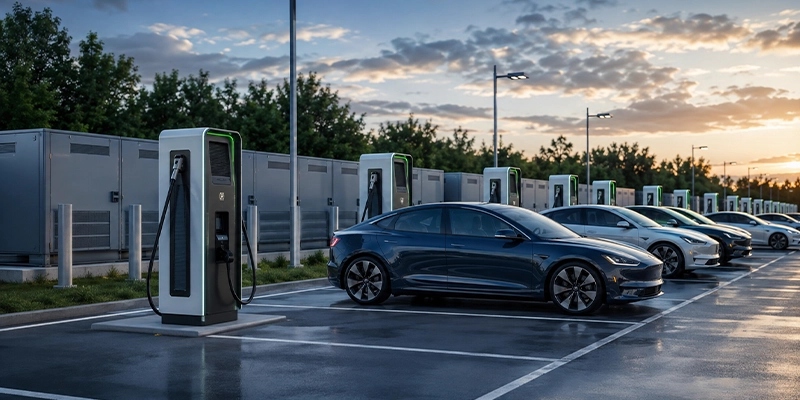
Check Electrical and Physical Constraints Early
A site survey should document the available electrical service, distribution space, cable routes, equipment clearances, drainage, vehicle movement, pedestrian paths, lighting, and maintenance access. These observations help determine whether a compact charger, a dual-gun unit, or a split-type DC charging system can be installed without disrupting normal site operations.
Build a Practical EV Charging Site Survey
Review Power Supply and Distribution Space
Record the utility service entrance, point of connection (POC), service voltage, transformer capacity, available feeder capacity, existing peak demand, and spare distribution capacity. The survey is not a substitute for local electrical design or utility approval; it gives the design team the facts needed to define a safe and workable charging boundary. Avoid assuming that a higher-rated charger can be added without corresponding infrastructure review.
Confirm applicable local approvals, utility connection requirements, and inspection stages before procurement and construction, and include them in the project schedule.
Map Traffic Flow and Charger Access
Mark entry and exit paths, reversing areas, accessible routes, cable reach, and the positions where drivers can connect without creating pedestrian-vehicle conflicts or interfering with traffic circulation. Single-gun, dual-gun, floor-standing, integrated, and stack-based equipment create different circulation requirements. Good layout decisions reduce cable strain and make service access easier after commissioning.
Confirm Connectors and Communication Coverage
Connector options such as CCS1, CCS2, CHAdeMO, and GB/T must be confirmed for the selected charger model and market. Confirm compatibility with the intended vehicles, including the connector standard, charging protocol, operating voltage, and current requirements. Check Ethernet, 4G, or Wi-Fi coverage and confirm which connection methods are supported by the selected charger. Any external router or gateway requirements should be defined before installation.
Select the Right U-charging DC Configuration
The power ratings, outlet count, per-outlet limits, and available architectures described below must be confirmed against the specification of the selected model. For multi-outlet chargers, confirm the total charger capacity, maximum power available to each outlet, and the power-allocation method used during simultaneous charging.
Compact DC Chargers for Moderate Demand
20kW, 30kW, and 40kW DC equipment can suit sites that need direct-current charging but have moderate demand or tighter space. These configurations may be considered for selected commercial parking, public-service, or fleet applications. The final choice depends on vehicles, site power, connectors, and the operating schedule.
Medium-Power DC Chargers for Higher Charging Throughput
60kW, 80kW, and 120kW configurations can support public charging sites, commercial parking facilities, and fleet depots where higher charging throughput and shorter vehicle dwell times are required. A mixed charging site may allocate DC fast-charging bays to short-dwell, higher-throughput use while reserving AC charging spaces for vehicles with longer parking durations. Do not treat rated power as a guaranteed vehicle charging rate.
High-Power DC Charging Systems and Split-Type Architecture
160kW, 240kW, and higher-power DC charging systems require closer coordination of electrical infrastructure, equipment clearances, connector handling, and traffic movement. Split-type DC charging systems can centralize power conversion equipment in a power cabinet while distributing charging outputs through separate charging dispensers. The project team should confirm the selected architecture, output allocation, cable routing, equipment clearances, and maintenance access during the design stage.
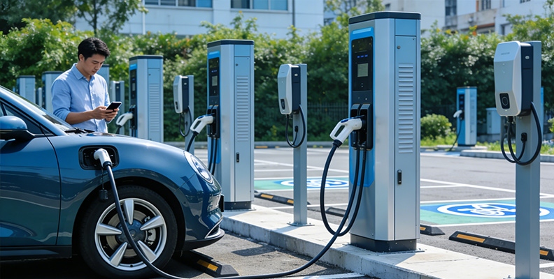
DC Charging Station Installation Planning
Prepare Foundations, Cable Routes, and Protection
Before delivery, coordinate foundations, conduits, cable trenches, grounding, distribution equipment, drainage, bollards, and emergency isolation. Confirm the protective functions built into the selected charger and the additional protection required in the site distribution system. Qualified electrical professionals should select and coordinate protective devices, earthing, isolation, and surge protection according to the equipment documentation and applicable local requirements.
Coordinate Equipment Format With Site Layout
DC charger cabinets, power cabinets, and separate charging dispensers require suitable foundations and protected service areas. Confirm cable storage, connector height, vehicle turning space, accessible parking requirements, and cable routes between equipment and the electrical distribution system. Resolve these details before completing civil works.
Define Network and Backend Requirements
Confirm the charging station management system (CSMS), user-access methods, network connection, and protocol configuration before commissioning. U-charging chargers support OCPP 1.6J, with OCPP 2.0 available as an option, depending on the selected model and software configuration. RFID and app-based activation should be confirmed for the selected configuration. Any payment functionality requires separate confirmation of the terminal, payment service, and backend integration.
DC Charging Station Commissioning and Testing
Complete Electrical and Safety Checks
Commissioning should begin with visual inspection, wiring verification, grounding and bonding, protective-device settings, emergency isolation, enclosure condition, and connector inspection. Confirm that the installed equipment matches the approved electrical drawings, installation specifications, and commissioning requirements. Any unresolved safety issue should be corrected before the charger is released for commercial operation.
Test Charging Sessions and Connector Compatibility
Use the intended vehicle and connector combinations to test authorization, start, stop, emergency stop recovery, communication interruption recovery, and authentication failure handling. Record which output and connector were used, together with the observed status and any corrective action.
Record delivered voltage, current, power, and energy under documented test conditions. Where applicable, verify simultaneous charging, power allocation, configured site limits, and payment completion. Assess results against the agreed acceptance criteria, taking account of vehicle charging limits and site conditions.
Confirm Remote Monitoring and User Access
Test the configured user-access methods and confirm connectivity with the charging station management system (CSMS). Verify online status, transaction records, alarms, and any supported remote diagnostic or update functions. Record the charger and connector identifiers, network connection, firmware version, backend configuration, and responsible operator.
Prepare for Handover and Ongoing Operation
Create Clear Commissioning Records
A useful handover pack includes the installed configuration, connector types, communication settings, protection checks, test sessions, outstanding defects, corrective actions, and pending items. Keep records for each charger and each output so future troubleshooting can distinguish a site-wide problem from a single connector or communication path.
The handover pack should also include as-built drawings, equipment serial numbers, firmware versions, operation and maintenance manuals, warranty information, service contacts, and signed acceptance records. Separate defects that prevent operation from non-blocking outstanding items, and assign an owner and completion date to each item.
Train Operators on Daily Operation and Basic Troubleshooting
Operators should know how to start and stop charging sessions, identify an offline charger, respond to authentication or payment failures, isolate an unsafe charging bay, and escalate technical faults.
Leave Room for Future Expansion
Reserve space in electrical rooms, cable routes, communications coverage, and equipment clearances for later additions. A phased plan may begin with moderate DC power and add higher-power equipment as demand develops. Expansion should follow new site calculations and vehicle requirements rather than simply duplicating the first installation.
Conclusion
DC charging station deployment succeeds when the survey, design, installation, commissioning, and handover records describe one coherent charging infrastructure system. Matching U-charging equipment to vehicles, traffic flow, electrical capacity, connectors, and backend needs reduces commissioning risks and supports stable long-term charger operation.
From compact DC equipment to high-power systems and charging stacks, U-charging gives commercial and public operators options for different deployment conditions. Talk to our engineer about your DC charging deployment. Share your project location, application, vehicle and connector requirements, planned charging bays, available electrical capacity, and target installation date to discuss a suitable configuration.
FAQ
Q: What is included in a DC charging station site survey?
A: A survey reviews electrical service, distribution space, cable routes, foundations, drainage, equipment clearances, vehicle movement, pedestrian access, connector needs, communications coverage, and maintenance space. It should also record future expansion constraints. The survey informs engineering decisions but does not replace local electrical design, utility coordination, or required approvals.
Q: Which U-charging DC configuration suits a commercial site?
A: The answer depends on vehicle type, dwell time, turnover, available site power, and installation space. Power ratings, connector options, outlet count, and equipment architecture must be confirmed against the selected product specification. For multi-outlet chargers, confirm the total charger capacity, per-outlet limits, and power allocation during simultaneous charging. The configuration should be selected according to the service objective rather than power rating alone.
Q: What should be tested during EV charging commissioning?
A: Commissioning can include visual and wiring checks, earthing and protection review, emergency isolation, connector inspection, authorization, start and stop behaviour, interruption recovery, fault handling, network status, transaction records, alarms, and supported remote functions. Record delivered voltage, current, power, and energy under documented test conditions. Where applicable, test simultaneous charging, power allocation, configured site limits, and payment completion. A single vehicle test does not demonstrate the charger’s full rated capability, and vehicle-imposed charging limits should not automatically be treated as charger faults.